
Snell's law for spin waves
Snell’s law describes the refraction of waves at the transition between two media with different indices of refraction. In optics, the dispersion relation of light is isotropic, and thus, the relation between the incident and refracted angles is solely determined by the ratio of the refractive indices. In contrast, for spin waves in thin films with in-plane magnetization the dispersion relation is inherently anisotropic, and thus, deviations from the Snell’s law in optics are expected but have not been reported directly so far.
We report the experimental observation of Snell’s law for magnetostatic spin waves in thin ferromagnetic Permalloy films by imaging incident, refracted, and reflected waves. We use a thickness step as the interface between two media with different dispersion relations. Since the dispersion relation for magnetostatic waves in thin ferromagnetic films is anisotropic, deviations from the isotropic Snell’s law known in optics are observed for incidence angles larger than 25° with respect to the interface normal between the two magnetic media. Furthermore, we can show that the thickness step modifies the wavelength and the amplitude of the incident waves. Our findings open up a new way of spin wave steering for magnonic applications.
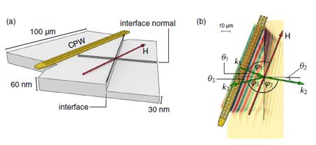
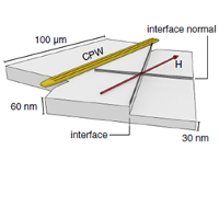
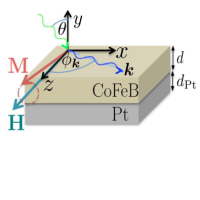
(a) Sketch of the sample with the z axis not drawn to scale. The red arrow indicates the direction of the externally applied magnetic field which is aligned parallel to the coplanar wave guide (yellow). The latter is used to excite spin waves which propagate perpendicular to it. (b) Top view of (a) with exemplary data acquired by TRMOKE. The green arrows show the wave vectors k1, k2, and k3 relevant for the analysis. φ1−3 denote the angles of the wave vectors with respect to the external field, while θ1−3 denote the angles with respect to the interface normal. The indices 1–3 correspond to the incident, refracted, and reflected wave, respectively.
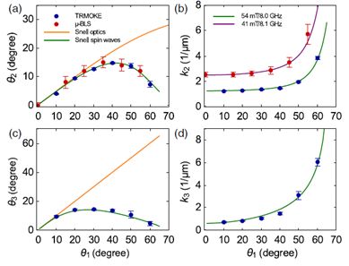 (a) Refracted angle θ2, (b) refracted wave vector k2, (c) reflected angle θ3, and (d) reflected wave vector k3, all shown versus incident angle θ1. In all graphs, the blue dots are experimental values measured with TRMOKE, while red dots are measured with μ-BLS. The orange line shows Snell’s law for an isotropic dispersion relation, and the green and purple curves show Snell’s law for spin waves. The latter are calculated with the help of the anisotropic dispersion relation, reflecting the different experimental conditions: The μ-BLS data are measured at an external field of μ0H=41 mT and an excitation frequency of 8.1 GHz, while TRMOKE data were recorded at an external field of μ0H=54 mT and an excitation frequency of 8.0 GHz. The purple curve is not shown in (a), since it overlaps with the green curve. The errors are the result from least square fitting.
Publication and authors:
J. Stigloher , M. Decker , H. Körner , K. Tanabe ,T. Moriyama , T. Taniguchi , H. Hata , M. Madami , G. Gubbiotti , K. Kobayashi , T. Ono and C. H. Back, “Snell's law for spin waves” Phys. Rev. Lett. 117, 037204 (2016), DOI: 10.1103/PhysRevLett.117.037204